The AU-CD beam line on ASTRID2
Specifications of the AU-CD beam line
A sketch of the AU-CD beam line, which is located on a bending magnet source, is shown below:
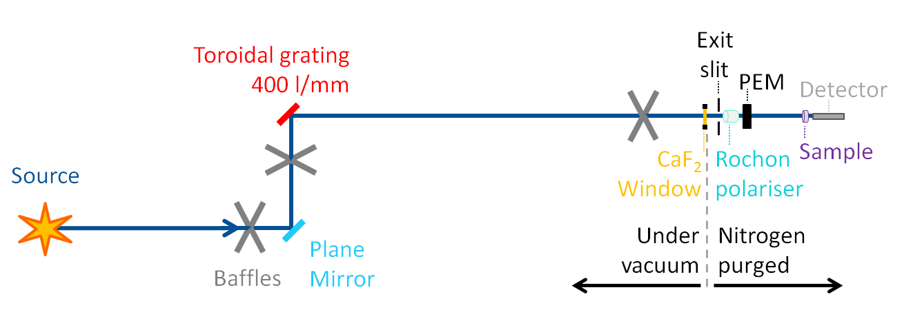
A schematic diagram showing the optical layout of the AU-CD beam line on ASTRID2.
The beamline consists of the following optical elements:
- A plane mirror deflecting the beam upwards toward the grating.
- A toroidal grating to disperse the synchrotron radiation.
- A CaF2 window to separate the beam line vacuum from air.
- Exit slit.
- CaF2 Photo Elastic Modulator (PEM).
The ruthenium coated quartz grating is a 400 grooves/mm laminar type and is optimized for high 1st order flux and low 2nd and 3rd order flux in the wavelength range of 115-350 nm. The width of CD bands are quite large, typically 20-30 nm, so the beamline need only provide a very moderate resolution of about 1 nm FWHM.
The beamline is operated as an entrance slit-less system. To yield a resolution of about 1 nm an exit slit size of 1 mm is required. Under these conditions the resolution of the entire optical set-up is exit slit limited. The exit slit size can be set over a range from 0 to 2 mm. As the grating rotates, the vertical focus point of the grating changes, however this change is very small, only about 12 mm. Given the moderate resolution required for SRCD, the grating to exit slit distance need not be changed during a wavelength scan.
The exit slit, the PEM and the sample are under a nitrogen atmosphere, separated from the beam line ultra-high vacuum by a CaF2 window.
Several baffels are placed along the beam line in order to reduce/remove any scattered light, which can adversely affect the SRCD measurements.
Optical parameters for AU-CD
| Optical Element | Distance from source | Major radius | Minor radius | Active area | Material |
| Mirror | 1.250 m | Plane | Plane | 50 x 30 mm (W x L) | Rhuthenium |
| Grating | 1.750 m | 2559 mm | 1339 mm | 70 x 55 mm (W x L) | Ruthenium coated quartz |
| Exit Slit | 3.625 m |
Resolution of the AU-CD beam line
The chart below shows the factors which contribute to the overal resolution of the photons on the AU-CD beamline with an exit slit opening of 1 mm. The contribution from the exit slit dominates and the setting of the slit generally defines the total resolution in the normal operation of the beam line.
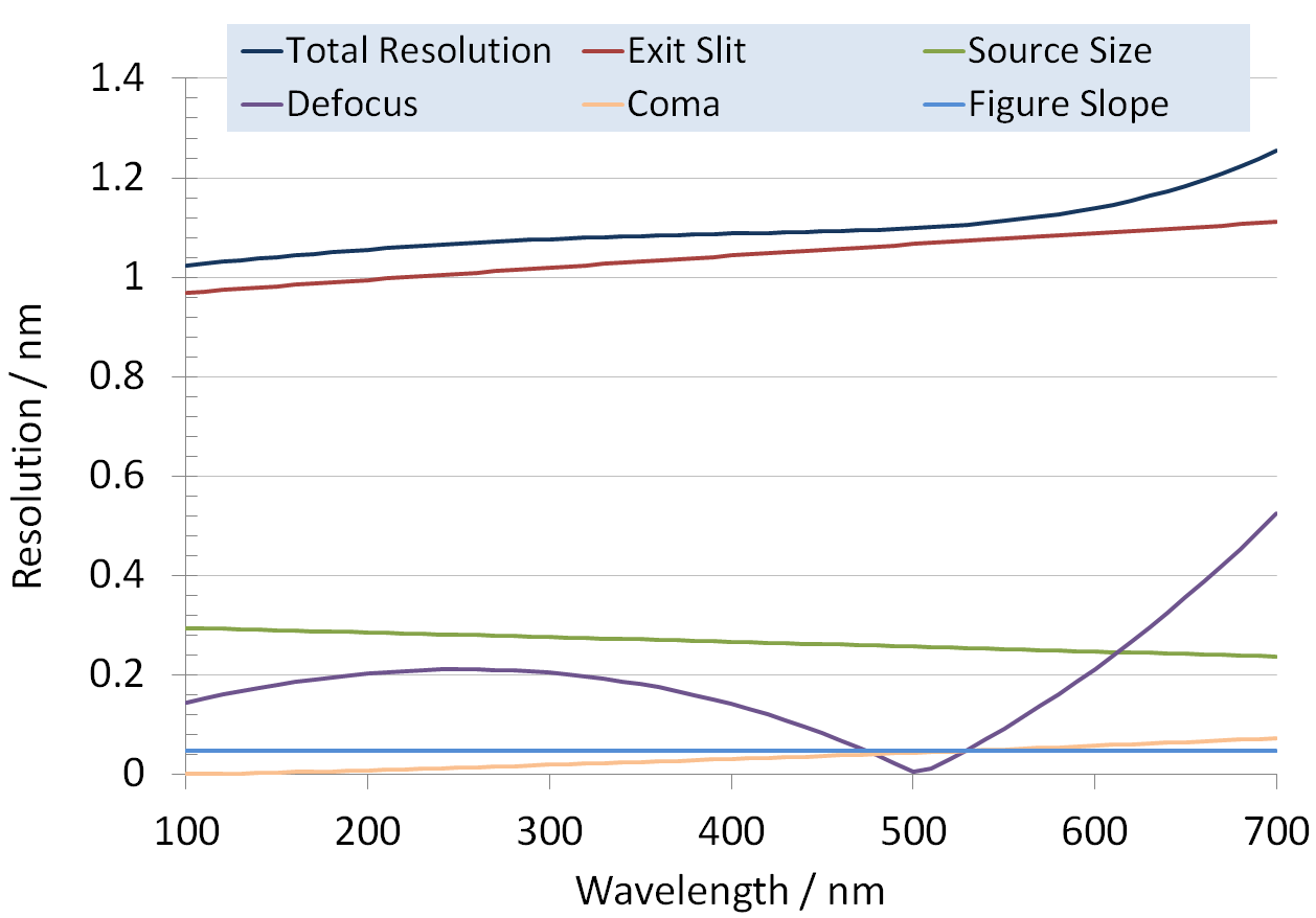
The calculated resolution for the AU-CD beam line with a slit of 1 mm.
In order to avoid degredation of proteins, the beam line is typically operated with an exit slit opening of 0.3 mm, which gives a resolution better than 0.5 nm as shown in the chart below.
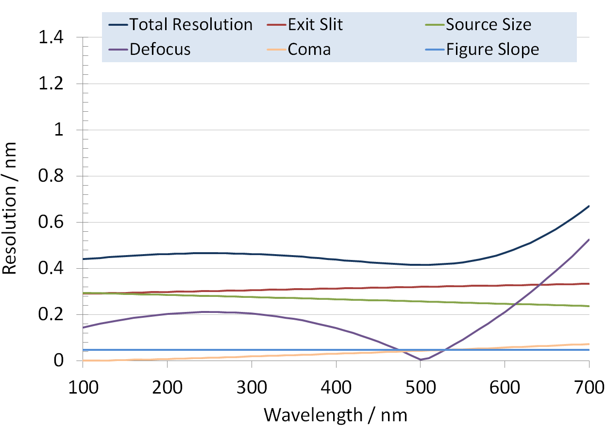
The calculated resolution for the AU-CD beam line with a slit of 0.3 mm.
The SRCD endstation.
The image below shows a photograph of the endstation used for SRCD measurements on the AU-CD beam line, with the important elements of the setup highlighted.
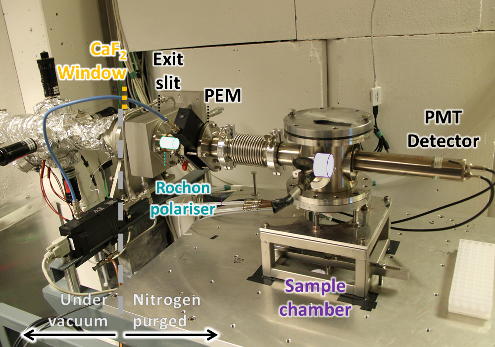
The SRCD endstation on the AU-CD beam line.
The monochromatised light from the AU-CD beam line passes through the CaF2 windows into a nitrogen purged closed system.
Last Modified 02 July 2021