User manual: Database Editor
 Status:
This information applies to Database Editor version 1.50.1017.273 (28. January 2026)
New in this version:
New access level control, controls different levels of editing permissions.
New batch copy increment specifications: F:i+ and F:I1
New Command line options
Consequence preview of changes made by 'Copy parameters' dialog
-- And several other bug fixes an improvements.
 Contents:
- Overview
- Access Level Controls
- Parameter definition
- Security/Access Groups
- Security - User special permissions
- Display Group Permissions
- Batch Copy Parameters
- Batch Create Graphics Page
- Command line options
- Device definition / device loading
Other links:
- Consys home page
- ConSys User Manuals
- Console Database tables
- Console Database tables
- ConSys Interpretations
- ASTRID2 Nomenclature
 Overview:
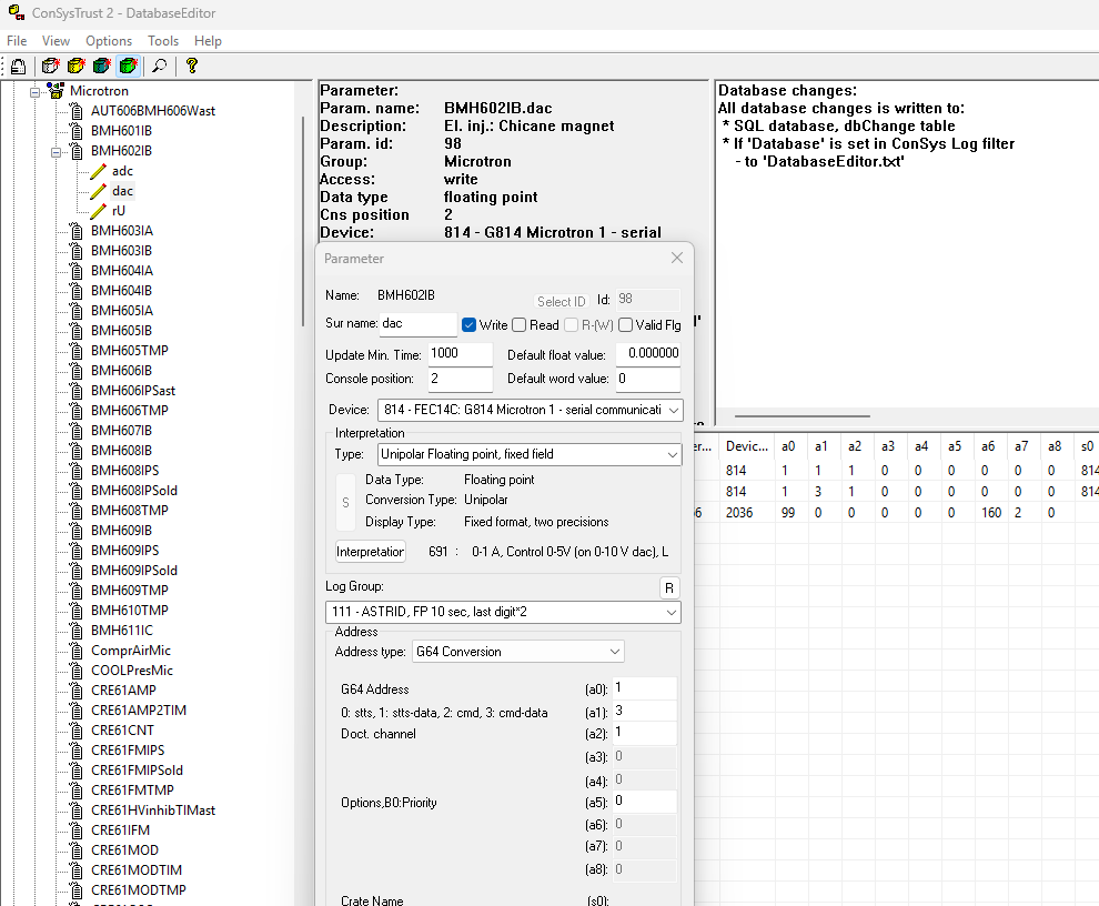
The DatabaseEditor is used to maintain the ConSys configuration database. The program is a combination of a coded knowledge of the ConSys configuration database structure and definition tables in the SQL data-base that defines the use of the general-purpose fields in the configuration tables. The DatabaseEditor is used together with Access to configure the ConSys system.
In the example above, the parameter ‘BMH601IP.adc’ in parameter group ‘Microtron’ is opened for editing. The usage of the generic fields a0..a8,s0,s1 is generated from the SQL ‘AddressDefinition’ table based on the address type defined under interpretation.
If usage string in the AddressDefinition table starts with the character '#' the '#' is removed from the string and the corresponding field is not enabled in the DatabaseEditor - the string is in this case just used as a comment for the user.
Access Level Controls:
 Update level toolbar controls:
The access controls levels what can be edited with the DatabaseEditor. These levels only controls which options are opened for editing by the DatabaseEditor - the underlying SQL database sets the basic security on the database tables. Users will only be allowed to make database changes if they are allowed to do this by the security set in the underlying SQL database. The maximum allowed editing level in the Data-baseEditor is set for each user in the ConSys database by the security filters for the users. To have access to edit the database the user must also have corresponding permissions in the SQL database. At ISA, this is handled through the AD groups ‘ISA-SQL-administrators’,’ISA-SQL-editors’,’ISA-SQL-editors-light’.
 Permission update control
Must be enabled to change security group membership and user access rights. Editing permissions does not require database edit to be enabled, i.e. can be changed even in ‘Database updates disabled’.
At ISA, users must be members of one of the AD groups ‘ISA-SQL-administrators’ or ‘ISA-SQL-editors’ to have full edit access to the ConSys SQL tables. DatabaseEditor light level and medium level require the user to be member of one of the groups above or ‘ISA-SQL-editors-light’.
 Database updates - disabled
Datatabase update/editing is disabled. In this state it is only allowed to view database settings - nothing can be changed.
 Database updates - light
Database update/editing is allowed for a limited set of operations. Furthermore, editing is restricted to parameter groups were the current user has write access permissions. The following can be edited in light mode:
Parameter - Rename
Parameter - Edit, sur-name and description (s1)
Computer - most fields.
Device - Enable.
User - Comment.
 Database updates - medium
Like light mode, just with more editing allowed. Includes everything from light mode and additional the following can be edited in medium mode:
Parameter - min time,position,default values, generic address fields
Device - most settings
User - Comment.
 Database updates - all allowed
Update of all settings in the SQL database is allowed - also independend of current user access permissions ser in the ConSys database. Only limited by native security in the underlying SQL database.
Parameter definition:
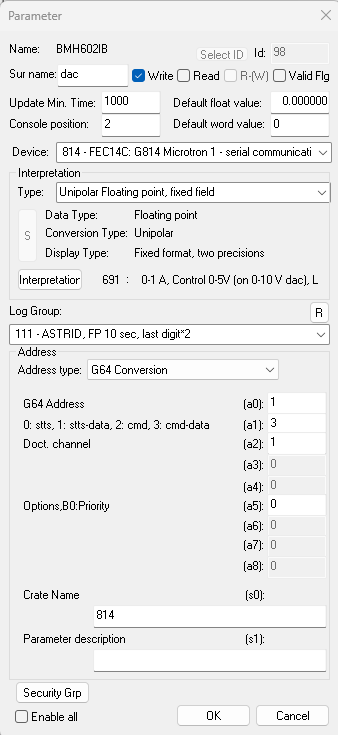
The parameter dialog is the one of the main configuration dialogs in the dialog editor and is used when defining or changing a ConSys parameter. The general-purpose fields for interpretation and addressing is up-dated with according the interpretation and address type during the selections made in the dialog.
Access filter bits: specifies the access type for the parameter and some options related to this use by the Console
Write: The parameter is a write parameter
Read: The parameter is a read parameter.
R-(W): Read allow write. Additional flag that can be set for read parameters. The parameter is actual a write parameter but displayed as read parameter in the console with a slightly different color. Writing to the parameter is possible by right clicking on the parameter in the Console.
Valid Flg: Allow change valid state for parameter. Special flag that can be set for Write and R-(W) parameters. When the flag is set the valid state of the parameter can be changed in the Consolee either by right clicking on the parameter or in the set value dialog for the parameter. Remark that setting the value flag is a special operation not meant for and supported by most normal devices. Mainly to used for special storage device parameters or calculation device parameters. See also Console command line option /v
Update Min. Time: The minimum time between send values using the default dataserver. In the Console, this will be the maximum update rate fo the parametr.
Default float value: Used for some devices to define the initial control value for floating point parameters at device startup. Usaly only used at the very first startup, as most devices store control values in persistent files.
Default word value: Like Default float value, used for intial word and bit device values.
Console position: Console position number is used to define the display order of parameters within the cluster. For detailed information see Procedure for calculating Console list view
Security/Access Groups:
Parameter Group security:
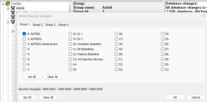
The security groups are used to handle permissions to the parameters in the ConSys control system. Each parameter group must be assigned to at least one security group. Access rights to parameters in a parametergroup is based on the assigned security groups. Additionally access to a given parameter can be added adding more groups to the specific parameter.
User access rights:
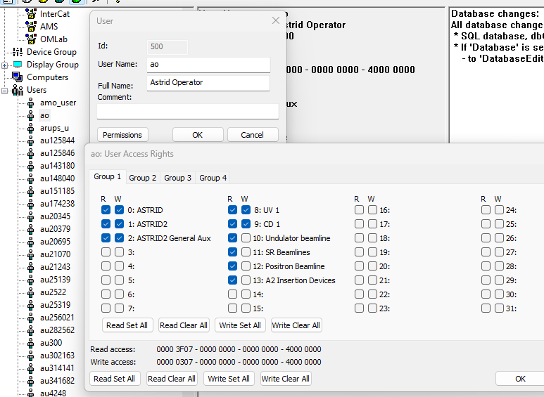
The access rights to parameters are typically set through the user permissions. Each user that should access ConSys must be defined in the ConSys database. The read and write permissions for a given user is set in the permissions dialog. The user has read and write access to parameters in groups with the ‘W’rite flag checked. If only ‘R’ead is checked, the user will only have read access to parameters in the corresponding parameter group.
Similar access control can be set to Computers defined in the computer tree. The actual access for a given user is set as an or between the computer defined permissions and user defined permissions. Computer based permissions are rarely used – it is recommended that most access to the ConSys parameter groups are granted trough the user groups.
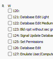
Security - User special permissions:
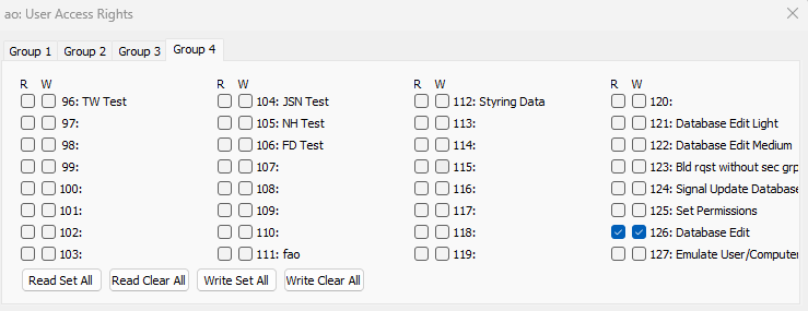
Under ‘User Access Rights, tab ‘Group 4’ there are several special settings that can be set for the user. To activate these settings, check the (W)rite flag. The settings are:
Database Edit Light: Users with this flag set are allowed to the DatabaseEditor light edit mode
Database Edit Medium: Users with this flag set are allowed to the DatabaseEditor light and medium edit modes
Database Edit: Users with this flag set are allowed to the DatabaseEditor light, medium and all edit modes
Bld rqst without sec grp: Build request without security group control. This is a special flag used to let Resto upload parameters from groups that the not set for the user.
Set Permissions: Users with this flag set are allowed to enable the 'permission change' mode
Emulate User/Computer: Users with this flag set are allowed to emulate other user permissions in DatabaseEditor and Console.
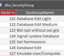
Remark: The special permissions flags must be defined in the SQL table 'SecurityGroup' with the following valus:
Display Group Permissions:
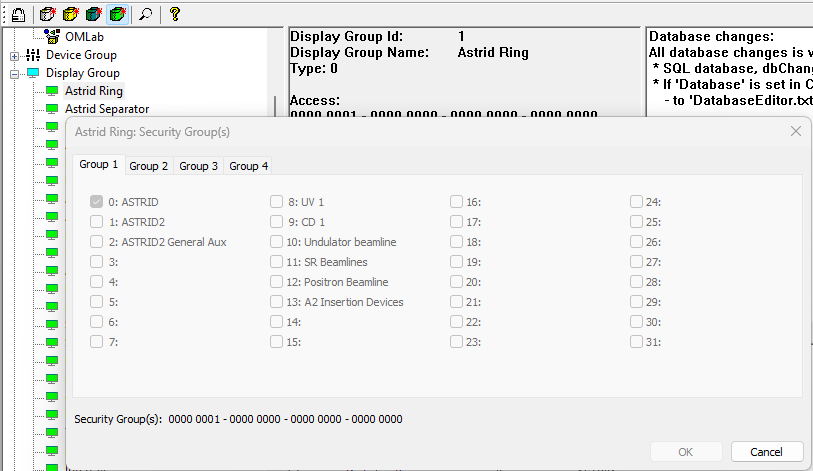
The Display Group permissions is used by the console to limit the available page groups and graphic pages to those with the correct permissions set. The user must have at read access to at least one security group for a given ‘Display Group’ in order to have access to the page groups and graphic pages belonging to the given display group. Graphic pages defined in the SQL ‘GraphicPage’ table links to a display group by the field ‘DisplayGroup’. The same is the case for the console pages defined in the SQL table ‘ConsoleGroup’.
Batch
Copy Parameters:
Should be used with care - carefull check the consequence report before executing the batch copy. The action can not be undone when executed!
The batch copy parameters is an extension of the 'Copy elements' method. The batch mode is meant for copying settings for devices with many similar clusters. The parameters from the source cluster is copied to the destination clusters as specified in the batch copy command file. The command file is text based, where the first character in each line specifies the use of that line:
S:<Cluster Name>
Defines the cluster <Cluster Name> to be used as copy source. Parameters from <Cluster Name> is copied to destination clusters
dependend on filters and options set in following commands.
Only one source can be defined.
<Cluster Name> A ConSys cluster name.
Q:<SQL filter string>
<SQL filter string> Additional SQL filter, can be used to select or avoid specific surnames etc. Added to Only one SQL filter can be defined.
P:<Cluster Name>
Destination cluster. Parameters from the source cluster will be copied to the destination cluster <Cluster Name>.
By default, only new parameters are copied to the destination cluster.
The default copy behavior and field modifications can be specified in the lines following the 'P' command.
Multiple destination clusters can be defined.
O:<M|P|N>
Copy options. Specifies behavior while copying parameters.
As mentioned above default copying only includes parameters not already present in the destination cluster.
The available options <M|P|N> are:
M - Modify existing parameters.
P - Modify existing but keep console position numbers.
N - Modify existing but keep negative position numbers.
F:<Field value>
Modify source field value for parameters that are copied to the the destination.
Used to modify field values when copying from the source cluster.
<Field value> is one of:
d;<deviceId> - Set deviceId to <deviceId>
a<n>;<address> - Set the general purpose address field a<n> (a0 to a8) to :<address>
a+<n>;<addAddress> - Add the <addAddress> to the source address a<n>
i+<n>;<incrAddress> - Like the a+ method, but using an incremented additionen to the address.
For each new source cluster the address will be:
'<incrAddress> * <#P>',
where <#P> is the mumber of clusters (P) in the input file up to this line.
Following cluster copies will keep using the same increments until a new i+ or a+ specification is reached.
A1;<A1 value list> - Storage device type dependend add to address field a1.
The value added is dependent on the data type specified in a0,
as defined in the list <A1 value list>
<A1 value list> = <double add>,<bit add>,<word add>,<string add>,<time add>,<pulse bit add>,<data value add>
- ie. there is there is an add value defined for each data type (a0:type)
0:double,1:bit,2:word,3:string,4:time,5:pulseBit,6:dataValue.
I1;<A1 value list> - Like A1, but using <A1 value list> as incremented additions to the a1.
The increment value to depends on the data type specified in a0, like in the A1 method, and is
'<value> * <#P>' where <#P> is the number of cluster sources (P) in the input file up to this line.
The value added is dependent on the data type specified in a0:
double,bit,word,string,time,pulseBit,dataValue.
Following cluster copies keeps using the same increments until a new A1 or I1 specification reached in the input.
s<n>:<text> - Set general purpose address string <n> to <text>. <n> is 0 or 1.
I:<Ignore changes mode>
Ignore changes mode. In this mode certean parameter changes are not made to the destination parameters
< Ignore changes mode> is either
A - Ignore adding new values to this cluster
I - Ignore interpretation changes to parameters in this cluster
L:<Log group mode>
Log group mode sets the method of how the log group id is updated.
<Log group mode> is one of
K - For modify parameter: Keep Existing loggroup, For new parameter: Source loggroup
S - Set source loggroup id
V;<long> - Set loggroup to the specified <long> value
A;<long> - Add specified ;<long> value to source loggroup id
C:
\:
Comment. The 'C' and '\' are both comments, line not parsed.
E:
End - Stops parsing, the remaining of the input file is ignored.
Examples:
S:P2_READ
Q:(SurName != 'lowLim') AND (SurName != 'upperLim')
P:P2_READ_C1
P:P2_READ_C2
O:M
F:d;100
F:a+2;10
F:a8;1234
F:A1;1,2,3,4,5,6,7
F:s0;This is a test text
F:s1;Another test
P:P2_READ_C3
L:K
L:S
L:V:111
L:A:-100
Batch
Create Graphics Page:
Should be used with care - carefull check the consequence report before executing the batch copy. The action can not be undone when executed!
The batch create parameter page tool is used to generate/update a previous generated graphich page base on a text based specification file. The tool works on a specified graphic page, specified by the graphic page id. The tool can generate a page consisting of parameters from similar clusters. A source cluster must be specified. All parameters found in the source cluster on the graphic will be created placed for all destination clusters. The x and y position of the destination parameters will be updated according to the script. The first charecter in each line defines the use of the line:
C: Comment - everything on this line is ignored
G: Graphics Page Id (Page field in dbo_ConsoleGraphParameter)
S: The source cluster name, only one source can be defined
D: Destination cluster name. The fields following this line is the settings related to this cluster.
X: Absolute x position. The position is relative to the source parameter position.
x: Incremental x position. For each destination cluster following this definition, the incremental x position will be added to the absolute x postion.
Y: Absolute y position. The position is relative to the source parameter position.
y: Incremental y position. For each destination cluster following this definition, the incremental y position will be added to the absolute y postion.
H: Header: Specifies a new header text.
Batch file format:
G:<Graphics Page Id>
C:<Comment>
S:<Source Cluster Name>
P:<Destination Cluster Name>
X:<Absolute x position>
x:<Incremental x position>
Y:<Absolute y position>
y:<Incremental y position>
H:<Header>
The two SQL database tables below defines the graphics pages:
GraphicsPage: This is the table where the page (and background bitmap) is defined, one entry per page
Note there is both a record Id and a GraphControlId in the 'GraphicsPage' table. The Id is used for ordering in the Console, whereas the GraphControlId is the one linked with the Page field in ConsoleGraphParameter table.
ConsoleGraphParameter: This is the table which defines all the controls, one entry per consys parameter
Example:
G:301
C:This is a comment
S:UBX111TBTast2
D:UBX112TBTast2
y:30
H:UBX112
D:UBX113TBTast2
H:UBX113
D:UBX141TBTast2
X:450
Y:0
H:UBX141
D:UBX142TBTast2
H:UBX142
Command line options.
Command line options are not case sensitive.
/db or /d <Database connection>
Startup ODBC connection:
<Database connection>:
1: Connect string 1
2: Connect string 2 (Default at ISA)
c: Current ConSys connect string
u: User select at startup (Default at SU)
/p <Parameter name>
Startup with edit of the parameter 'Parameter name'.
/s
Startup with allow edit permisssions enabled.
/u
Startup with allow update database enabled.
/e <User name>
Startup with emulating user permissions for user 'User name'.
/?
Show DatabaseEditor help (at command line settings).
Device definition / device loading:
Originally, device configurations were stored in binary files for each ConSysLoader instance. However, since 2017 devices can be configured in ConSys Database, and this is today the preferred method. A few old device types only supports configuration through local configuration files, but most devices have been converted to support database configuration. Not all new devices support local configuration files.
Devices are configured in the table DeviceConfiguration with helper tables DeviceClass (list of all different devices (different device classes) and DeviceConfigurationDefinition (definition of the use of the general database fields). The devices class indices in the device class must match the class id’s defined in ConSysKernel, indices.h.
Each device-configuration has an unique ID (DeviceConfigId), which is linked to a unique DeviceId (from DeviceLocation)). The reason for multiple DeviceConfigId's for a given DeviceId' is to make debugging easier (allows for separate (alternative) configuration for debugging of a device). Typical the unique DeviceConfigId is the same as the (unique) DeviceId (for the "production" DeviceConfigId)
Each unique DeviceId (from DeviceLocation) has a defined Frontend and LoaderInstance, where the device is intended to run. Each device-configuration has an alternative computer id (and alternative loader instance) where the device CAN be loaded (for instance for debug purpose). If the alternative computer id is positive the device will not be loaded on the (intended) frontend computer (but a device will keep running on the frontend until the frontend kernel is restarted). A device is only loaded if the enable flag is set. Remark that client computers apart from the computer running a local copy of a device will always look for a device at is original location defined in the device location table.
- Simple debugging (single device-configuration): Set the ComputerId of the debugging computer in the alternative computer id field and start the debugging kernel with the /ld option. The original device will keep running on the original frontend UNTIL the original frontend is restarted. An easy way of disabling the alternative computer is done by negating the alternative computer is (this way it is easy to enable the alternative computer again). Other computers will look for the device at the (original) frontend. If it is a device which communicates with an instrument (or something) remember to disable the communication (using the device enable/disable parameter). For this method device configuration will be same for debugging as for the "real" device.
- More advanced debugging (dual device-configuration): Have an extra device-configuration (typical with a DeviceConfigId which is +20000 or +50000 of the DeviceId). Set the ComputerId of the debugging computer in the alternative computer id field and start the debugging kernel with the /ld option. The original device will keep running on the original frontend unless the original DeviceConfiguration is disabled and the original frontend is restarted. Other computers will look for the device at the (original) frontend. If it is a device which communicates with an instrument (or something) remember to disable the communication (using the device enable/disable parameter). For this method the device configuration can be different for debugging as for the "real" device. This method is properly a little more "safe", since less editing of the original device-configuration is likely to happen (but requires an extra device-configuration). In this way the device will also be loaded if the ConSysLoader is restarted at the original location.
- Separate device: For more throughout debugging a separate (test) device (with separate test parameters) may be needed. This will typical then only need one device-configuration (unless different device configurations are to be tried (tested)).
When using the local device (/ld) option the local devices "reuses" the parameters for the original device, i.e. one does not have to define extra parameters. Dependending on the device under debug it may be needed/a good idea to copy the persistent stored data for the device from the original device location to the debug location.
Device load order:
- Enabled devices from local configuration file
- Devices from dbo_DeviceConfiguration, which is enabled and where the Frontend computer ID match the loading computer ID and which does not have a positive Alternative computer ID
- If the ConsysLoader is started with the Local Devices option (/ld), then enabled devices from DeviceConfiguration, where the Alternative computer ID match the loading computer ID will be loaded
A given (unique) DeviceID will only be loaded once on a given Frontend/LoaderInstance (but CAN be loaded on different Frontend/LoaderInstances).
Last Modified 29 January 2026