User manual: DAF Loader
 Status:
This information applies to DAFLoader version 1.41.21.189
The FAF loader has been integrated into the DAF loader program.
 Contents:
- Overview
- Loading a DAF table.
- The Preprocessor.
- Operating the AEG timer.
- Changing operation mode (dynamic/Static control).
- DAF file format.
- Editing in Excel - and the Excel export function.
- Loggings in the DafLoader.txt file
- Command Line Startup options
Other
links:
- Consys home page
- ConSys User Manuals
- FAF notes.
- The VdFAF virtual device
- DAF block diagram (PDF format)
- DAF Loader internals
- DAF hardware description
 Overview:
DAF: Dfi Autonomous Function generator - hardware function generators/timers.
The DAF system has two hardware parts: The AEG timer responsible for
the overall synchronization of the function generators and the
individual function generators, the DAF modules. Each DAF module defines
a set of vectors defining the function. Each vector is defined by two
values: The 'Loop time' and the increment value. Every 100 µsec of the
loop time the increment value is added to output value. A special
version of the DAF board, the bit event board, is used to generate
pulsed and/or stationary output bits at specific times. On this board
the loop time specifies the delay between outputs and the increment
table the output values (the 16 most significant bits are used). The
vector tables on the DAF module can store up to 511 vectors or bit
events. The DAF modules also include an event table used to control the
function generator from common AEG timer. The AEG timer sends 1 byte
events to the DAF modules at specified times. The DAF module event table
maps the incoming events to actions in the DAF module. This version of
the DAF loader uses the following event actions: Stop, Start, Event
Stop, Event Start. The Start event initiates the vectoring from the
first vector in the table. The Stop event terminates the vectoring and
set output to the standby value loaded with the table. The 'event stop'
and 'event start' is used for temporary stop of the vectoring - by
convention called 'flattops'. Flattops can be of zero length. Zero
length flattops will not be seen on the outputs on normal operation. If
the AEG is inhibited input is active when a flattop is reached, the AEG
timer stops temporary until the inhibit input is deactivated.
The FAF is (was) a function at ASTRID to calculate and download RF
frequency change necessary to accelerate ions in the ASTRID storage
ring. It is not really used today (200324).
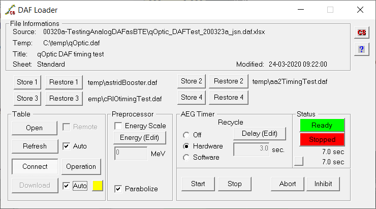
The DAF Loader program has two purposes: The first is to interpret function tables written in Excel and load these into the G64 DAF modules. The second is to operate the AEG timer. These two program parts have been integrated to obtain an automated operation, where new tables are loaded automatically whenever possible.
Loading a DAF
table.
The function generator vector tables, typically edited in Excel, are stored as text files with the 'daf' file format described below. As the daf files are assumed to be computer generated the amount of error check during the parse of files are limited. If there is an error in a daf file, the typical error message will be a short message including the number of the line where the error has occurred.
Before running the DAF function generators the vector tables must be calculated and loaded into the individual G64 DAF control boards. At the same time, the AEG timer tables must be calculated and loaded. Loading can only take place when the AEG timer and the DAF control boards are in stop mode. Loading at any other time will bring the DAF system in an undefined state. The AEG timer must not trigger a new run before the load has finished. There are no ways in the hardware to ensure that these conditions are fulfilled. By monitoring the AEG timer status and the loading process of the individual DAF modules as well as internal states the DAF loader program itself, the DAF loader ensures that loading is only possible when allowed by the hardware state. The AEG timer cannot be triggered from the DAF loader before the loading process has finished. When using the AEG hardware recycle timer to restart the AEG timer, the user must ensure that the recycle time is long enough to finish a load. The DAF loader has an internal time limit that will prohibit a new load if the hardware timer is used with a recycle time that is too short for a typical load. The load control buttons as well as the AEG controls are enabled/disabled according to the current state of the DAF operation. If the AEG timer are controlled from other applications (ex. The Console), or if DAF tables are loaded from other applications (Another instance of the DAF loader) correct management of the states - and thereby the load process, can not be guaranteed.
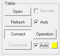
Open:
Give a standard open dialog, where the DAF file to be opened can selected. Usually daf files are temporary files generated from Excel. If the auto load option is being used, it is preferable that the daf file is stored on the local computer, as file timestamp is checked every 2 seconds. When the file is opened, it is parsed immediately, necessary database informations are obtained and the selected preprocessors are applied. If the DAF loader is connected to the control system, and the auto load box is checked, the DAF modules are loaded whenever possible. When a new file is loaded the informations in the 'File information' window are updated.
Refresh:
Check the timestamp on the last file opened by the DAF loader. If a never version of this file exist, the file is reloaded.
Auto Refresh:
When this box is checked, the refresh operation is performed automatic every 2 seconds - and when the AEG timer state changes.
Connect:
When the button is down, the DAF loader is connected to the control system. If the connection for some reason is broken, a new connection can be made by releasing the button and press it down again. The connection can be broken and reconnected while the function generators are running.
Operation:
Opens the operation control dialog - used to move parameters between dynamic and static control.
Load:
Load the calculated data in the program to the DAF modules and the AEG timer. All parameters in the table being loaded are set to dynamic control. The load button is only enabled when connected to the control system and a load is allowed by the state of the AEG timer etc.
Auto Load:
When the auto load check box is checked, the daf table load are performed automatic at the first possible time whenever the data has changed, either by a load, refresh or a change in preprocessor options.
Load State Lamp: (The lamp next to the load button)
 Not connected to control system.
 Daf table loaded.
 Data changed since last load.
 Loading DAF tables.
Quick Store and Restore
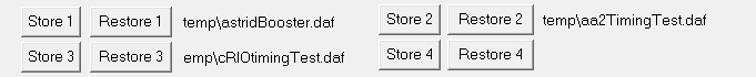
The DAFloader has 4 quick Store and Restore buttons, which can be used
to store up to 4 different daf files, and then quickly change between
them.
Note also the possibility of remotely through ConSys perform a Restore.
See the /r command line Startup option.
The
Preprocessor.
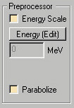
This part of the daf loader controls the use of preprocessors defined in the loaded daf file. When a new file is loaded it is preprocessed according to the selections/settings. Whenever a setting is changed, new daf tables are calculated and the data is again marked as changed.
Operating the AEG timer.
It is strongly recommended, that all control of the AEG timer are done from one and only one instance of the DAF loader. This is the only way to ensure, that the AEG timer is stopped and not can be started during a new daf load. Operation from other programs, like the console, is possible - but may cause problems if software recycling or the Auto load function is used.
Start: Send a start command to the AEG timer, if allowed in the current state.
Stop: Send a stop command to the AEG timer. This command should not be used under normal operation conditions, as the synchronization between the AEG timer and the DAF control boards are lost - leading to strange behavior of the DAF system. Under normal operation conditions, the AEG timer and the DAF modules will be programmed to stop by at the end of the sequence.
Abort: If pressed during a vector sequence, all flattops will be skipped, but all vectors and bit events will be processed as usually. The abort command will stay active until the end of the sequence.
Inhibit: Stops AEG timer on flattops while pressed. If pressed outside a flattop the AEG timer will stop when the next flattop is reached. This mode of operation is very useful as breakpoints - zero length flattops at any time in a vector sequence. Flattops of zero length - breakpoints - have no effect on the vector sequence if inhibit is not active.
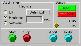
Recycle Timer modes:
Off: There will be no automatic restart of the timer.
Hardware: When the AEG timer stops, it will restart after the specified recycle period. The trigger is done by hardware - and hence precise.
Software: When the AEG timer stops, it will restart at the first possible time after the specified recycle period. If the daf system is loading or by other reasons not ready, the restart will wait until the DAF system is ready before sending a start trigger. If the data has changed and Auto Load is checked, the DAF tables will be loaded before a start trigger is send. Setting the recycle delay to zero and enabling the Auto Load function will give the maximum speed of the load/restart sequence.
Status display:
Upper lamp: Client state and load state. Gray (no client): No connection to the AEG timer/control system. Green (Ready): The AEG timer can be controlled. Red (Not Ready): The AEG timer can not be controlled - for example during load.
Lower lamp: Timer state - Gray: No connection to the AEG timer/control system. Red (stopped): The AEG timer is stopped. Green (running): The timer is running.
Upper time: AEG time. The total time passed since the AEG timer start was triggered.
Lower time: Vector time. The AEG time with the sum of passed flattops subtracted.
Yellow status lamp: Light up on a flattop. Calculated from the AEG time and the last table loaded.
Changing operation mode (dynamic/Static control).
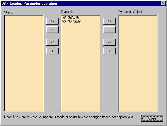
The operation control dialog is used to move parameters between static and dynamic control. When a parameter DAF table is loaded it is at the same time set in Dynamic mode.
Static: The static control value is used send to the output. A control, that is made static during a vector sequence can not join the vector sequence again before the next start of the AEG timer.
Dynamic: The dynamic control values (the vectoring values) are send to the output.
Dynamic adjust: If on a flattop - or set before a flattop is reached - the dynamic control value at the flattop will be set to static control value, and the static control value will be send to the output. When the parameter is returned to Dynamic mode, the static control value will be transferred to the dynamic control value and the vectoring will resume from the new value. Remark that all vector tables are defined by increment values over a given time - i.e. adjusting a value during the vector sequence will offset all the following vectors.
>>: Move all parameters from the left list to the right list while changing the control status.
>: Move selected parameters from left to right.
<<: Move all parameters from right to left. The button between Static and Dynamic also includes parameters from the Dynamic-Adjust list.
<: Move selected parameters from right to left.
DAF file format.
The daf files are ASCII text files with file extension '.daf'. The file format is created for easy and compact export from Excel. A character specifying the type of the line initiates each line in the daf file. The data values following are separated by semicolons, and the line is terminated by the '#' character. Parameters in the daf table are specified in blocks with identical time and preprocessors. The number of blocks is unlimited. Each block is initiated by a Vector Time Definition. Following the time definition preprocessors for the block can be specified. If more than one preprocessor is specified, they are evaluated in the order they appear. In the present version, two types of preprocessors exist: Energy Scale and Parabolisation. As the parabolisation changes the number of vectors and the vector times, Energy Scale must be specified before parabolise, if both preprocessors are used. After the header block follows 'vectors tables definitions' and 'bit event definitions' for the parameters in the block. A optional Flattop definition can be placed at any line in the files. Lines starting with other characters than the characters defined below are ignored. It is recommended to use 'C' as type for comment lines.
Example:

H:"Event parameter test";"New format";"06-04-98 14:20:03";"No source file"#
R:"CRI31SELtst";"faf";1;0;20;1;10;0.15;0.1;3#
T:3;0;2.05;4#
E:1.6;0;1;0#
P:12;0;160;160#
V:"AST99A01tst";"daf";x;2.000;10.000;2.000#
B:"CRI31DAFtst";"bte";;132;130;128;#
T:2;0;2#
B:"AST99PGEtst";"bte";;0.000;1#
A:"CRI31SELtst";"AST99A01tst"; 1 ;0.000;0.000;0.000#
F:2/0;3.9/0#
L:"BoParAst";"ExtrTime";7.700#
H: The Header line:
H:"<Title [string]>";"<Sheet name [string]>";"<Modified time [string]>";"Source File Name"#
This line must be present in the daf file in one instance. It includes three strings enclosed in "". The values of these strings are displayed in the 'File Information' window when the file is loaded.
T: Vector time:
T:<#Vectors [integer]>;<time 1 [floating point]>;<time 2 [floating point]>; .... ; <time #Vectors [floating point]>#
The vector time definition initiates a new block of vectors/bit events with common times and preprocessors. The first value in the definition is an integer specifying the number of vector times for the generator functions specified in this block. The following values are the vector times for this block. The first value must be zero. The times must appear in increasing order, and the number of times must match the specified number of vector times. The time is given in seconds. The minimum vector length (same for bit event) is 0.0001 s, but note that for the minimum vector length the change can only be half the range.
E: Energy Scale:
E:<Energy (MeV) [Floating point]>;<Mark 1 [integer]>;<Mark 2 [integer]>; ... ;<Mark #Vectors>#
Preprocessor definition for energy scaling. The first floating point number is the Energy in MeV at the marked vector positions. The following numbers are marks for each vector: 0: no rescale 1: rescale
P: Parabolise:
P:<#of inserted vectors [integer]>;<parabolisation period 1 [Floating point, ms]>;<parabolisation period 1 [Floating point, ms]>; ...; <parabolisation period #Vectors [Floating point]>#
The first parameter in the parabolisation preprocessor definition specifies how many vectors there will be inserted at each parabolisation point. The following numbers are the parabolisation periods in milli-seconds. At each vector end point where the parabolisation period is greater than 0 and small enough to be inside the two vectors around the parabolisation point, the specified number of new vectors are inserted to generate a parabolic function. The parabolisation range is from -T/2 to +T/2, where T is the parabolisation period.
V : Vector table definition:
V:<Parameter name [string]>;<Surname [string]>;<Preprocessor active [Boolean]>;<value 1 [floating point]>;<value 2 [floating point]>; ...;<Value #Vectors [floating point]>#
The vector definition defines the vectors used to generate the output function for a given parameter. The first two values specifies the parameter on the control system. The parameter specified must be a G64 DAF controlled dac. Any character in the third value - Preprocessor active - enables preprocessors defined in the current daf block for this parameter. The following floating point values defines the endpoints of the vectors defining the output function. The minimum vector time length (same for bit event) is 0.0001 s, but note that for the minimum vector length the change can only be half the range. The first value will also be loaded as the standby value set to output when the DAF board is in the stop mode.
R : FAF table definition:
R:<Parameter name [string]>;<Surname [string]>;<Calculation no [word]>;<Table no [word]>;<Mass[floating point, amu]>;<Charge [word]>;<Harmonic [word]>;<E-start [floating point, MeV]>; <E-low[floating point, MeV]>; <E-high [floating point, MeV]>;#
The FAF table must be specified with table 0 as the last table. At present, only one calculation method is implemented for the FAF, Calculation No must be set to 1.
A : FAF Adjust coefficients:
A:<Parameter name [string]>;< related vector name[string]>;<DAF table number[word]>;<Coeff 1>;..;<Coeff n>#
B: Bit events:
B:<Parameter name [string]>;<Surname [string]>;;<value 1 [special int. format]>;<value 2 [special int. format]>; ...;<Value #Vectors [special int. format]>#
Defines a bit event sequence for the bit event version of the DAF board. The parameter name specified by the first two parameters must be a G64 DAF bit event parameter. Remark that 2 semicolons follow the surname. The values are the send as they are to the output at the times given by the vector times for the current block. The bit event board has 8 stationary (bit 8..15) and 8 pulsed outputs (bit 0..7). Depending on the way the output values are specified the stationary and pulsed bits can be either identical or independent on each other:
[special int. format]:
xxx - the same value xxx is loaded to the stationary and pulsed outputs, ex. 128 will set the MSB on the stationary output and give a pulse on the MSB on the pulsed outputs.
xxx.xxx - independent values - the first value is loaded to the stationary output and the second to the pulsed output, ex. 128.001 will set the MSB on the stationary output and give a pulse on the pulsed output LSB.
The two formats can be mixed in the same input line.
F:Flattop:
F:<time 1 [floating point]>/<duration 1 [floating point]>;<time 2 [floating point]>/<duration 2 [floating point]>; .... ;<time n [floating point]>/<duration n [floating point]>#
One - and only one - optional flattop sequence can be defined in the daf file. The flattop defines the position (in vector time) of the flattops, and the correspondent duration's of the flattops. The minimum flattop length is 4 ms, but it is allowed to define zero length flattops - which are useful for definition of optional user breakpoints on the vector functions. If a flattop time less than 4 ms is given the time will automatically be increased to 4 ms.
I:Injection time (Recycle time):
I:<time[floating point]> #
If present, the recycle time is set to the specified time at the first download after each file load.
L: Parameter Load:
L:<Parameter name [string]>;<Surname [string]>;<value>#
Load a value into the ConSys parameter Parameter Name.Surname. (Note 200324: Only Floating point, Bit, Word, DWord, and Long values is implemented in the DAFLoader)
Editing in Excel - and the Excel export function.
The DAF loader files can be generated from a spreadsheet in Excel through the export macro 'DAFExport()' written in Visual Basic inside Excel. With the DAFExort macro assigned to a toolbar button in Excel - and using the Auto load and Auto Refresh options in the DAF loader - fast and easy daf file editing and loading are obtained.
The export function is relative simple and relies on a line by line interpretation of the Excel data sheet. Each row in Excel will generate one line in the daf file - starting from the second row. The file name of the daf file must be specified in the first row, second column - ie. Cell B1. The following rows must appear in the order dictated by the daf file specifications. The first column, column 'A', contains the type definition character definition. The export macro terminates at the first empty cell in the 'A' column. Empty or comment lines can be inserted if they start with a character not used for type recognition - the 'C' character is recommended. Formulas between cells and formatting of cells are allowed, as the export macro only reads the data values from the cells.
Here is an example Excel DAF file. Note the file contains invalid parameters (to avoid accidental download to real parameters). More examples are available from ISA staff by request.

Excel sheet format:
DAF file name:
B1: The full file name of the exported daf file.
H: The Header line:
Column B: Time for the last modification [time] - typical assigned to the Excel Now() function. Column C: Sheet title [string] The name of the sheet is stored with the header.T: Vector time:
Column E: Start time - must 0.00 [floating point]The following columns are the vector end/start times in increasing numbers, given in seconds. The minimum time resolution is 0.0001. The number of time values defines the number of vectors in the following block.
E: Energy Scale:
Column B: Energy in MeV [floating point] Column E ff.: An non empty cell marks a column to be rescaled.P: Parabolise:
Column B: Number of vectors to use in the parabolisation. [integer] Column E ff: Empty, if no parabolisation at this point. If not empty, parabolisation will take place around this point over the period (-T/2 to +T/2) , in milliseconds , specified. [floating point].V : Vector table definition:
Column B: Parameter name. [string] Column C: Surname. [string] Column D: An non empty cell activates preprocessor for this parameter. Column E ff: The vector endpoint values. [floating point]B: Bit events:
Column B: Parameter name. [string] Column C: Surname. [string] Column E ff: The data output values [0-255]. Two valid formats: zero decimals - the same output value is written to the stationary and the pulsed output. Three decimals: Separate values are written to the stationary and pulsed outputs. Use cell formatting to set either zero or three decimals. (See the bit event specification for more information on the two formats.)F:Flattop:
The flattop definition has adjoining lines; the first defines the flattop times and the second the duration's.
Line 1, Column E ff: flattop time in seconds. [floating point] Line 2, Column E ff: flattop duration in seconds. [floating point]A : FAF Adjust coefficients:
The FAF Adjust coefficients are used in some FAF calculations to make parameter value dependent coefficient tables.
Column B: Parameter name. [string] Column C: Parameter name of related vector. [string] Column D: DAF table number. Column E ff: The adjust coefficients - 0 <=> no adjustment. [floating point]R : FAF Load:
Column B: Parameter name. [string] Column C: Surname. [string] Column D: FAF calculation number selection, 1: ASTRID FAF Column E: DAF table number, 0 - 3Constants used for the FAF table calculation:
Column F: Mass in amu. [floating point] Column G: Harmonic number. [integer] Column H: RF Start energy. [floating point] Column I: RF Low energy. [floating point] Column J: RF Low energy. [floating point]I:Injection time (Recycle time):
Column C: Injection time (recycle time). [floating point]L: Parameter Load:
Column B: Parameter name. [string] Column C: Surname. [string] Column E: The data value (Note 200324: Only Floating point, Bit, Word, DWord, and Long values is implemented in the DAFLoader)
- Open Excel, open file ..\Nat_ISA-Astrid\Setups\AstGeneral\ConSysMacros.xls
- Right mouse click on program header, and choose Customize Quick Access Toolbar.
- 'Choose Commands from' and select macros. Add the ConSysMacros.xls!DAFExport.
- Select the newly made button and the select Modify Selection in the Customize dialog box
- Select a suitable icon, for instance the 'big fat arrow down' in the Change Button Image

Loggings in the DafLoader.txt file:
If the 'Application Info' log filter is set (using CsShortcutSetup), operational loggings is written to the 'DafLoader.txt file in the ConSys directory.
Command line Startup options:
New startup options in DAFLoader:
/a - Enable 'auto Refresh' and 'auto download' at startup
/r <cluster name> - Enable remote control from ConSys by storage parameters.
/m ['Optional String Parameter Name'] - Disable modal dialog boxes.Optional enable messages to ConSys string parameter (meant for CtrlQuickNote). Note always write messages to Remote cluster .Message (if /r specified).
Example:
/a /m TST_DATADEVICE.str1 /r AST99REMtst
/a /m statusVPast.CtrlQuickNote /r AST99REMast
Parameter names in remote cluster: Last Modified 03 October 2025
Remote1 .. Remote4: Bit
cDafRemAlivePeriod: Storage device ‘alive’ time (type 10)
LoadState: Word (DAF state text interpretation).