StepperOnline Motor Stepper Driver Device
Status
The StpprOnlnModbusDevice initial release version (June 2024, version 1.47.756.223) .
 Contents:
- Overview
- Motor specific parameters
- Common device status and control parameters
- Error and message numbers
- Device initialisation
- Use of digital inputs (limit and home switches)
- Device Configuration
- MOXA configuration
- DM556RS wiring and configuration
- The STEPPERONLINE MotionStudio utility
Other links:
- Consys home page
- Serial Device Versions
- Documentation and drives in folders:
- '\\uni.au.dk\dfs\Nat_ISA-Lib\ManualsAndDrivers\StepperOnline\DM556RS_ModBusRS485StepperDriver'
- '\\uni.au.dk\dfs\Nat_IFA-ngr\fm\dok\opgaver\new stepmotor 2024'
 Overview:
The StpprOnlnModbusDevice is for control of STEPPERONLINE Digital Stepper Drivers DM556RS, DM882RS, CL57RS and CL86RS. The device has up to now been tested with DM556RS and CL57RS, both in version 201 (as read from the driver through the RS485 ModBus). The RS485 ModBus control of the Digital Stepper Driver can be daisy chained to control up to 31 drivers in one chain. The StpprOnlnModbusDevice supports control of all 31 drives – but updating rates will be reduced when adding more controllers. Connected through a MOXA RS485, the update rate is limited by the MOXA forced transmit configuration. However, if only a few motors should be moved simultaneously, it will be okay to have many stepper controllers in the daisy chain. The ConSys device optimizes the communication, so control commands are always sent before reading of status and position from the stepper drivers. The update rate for none moving motors will be slow, so the communication bandwidth can be used to update position and status for moving motors.
Motor specific parameters
Motor control console view
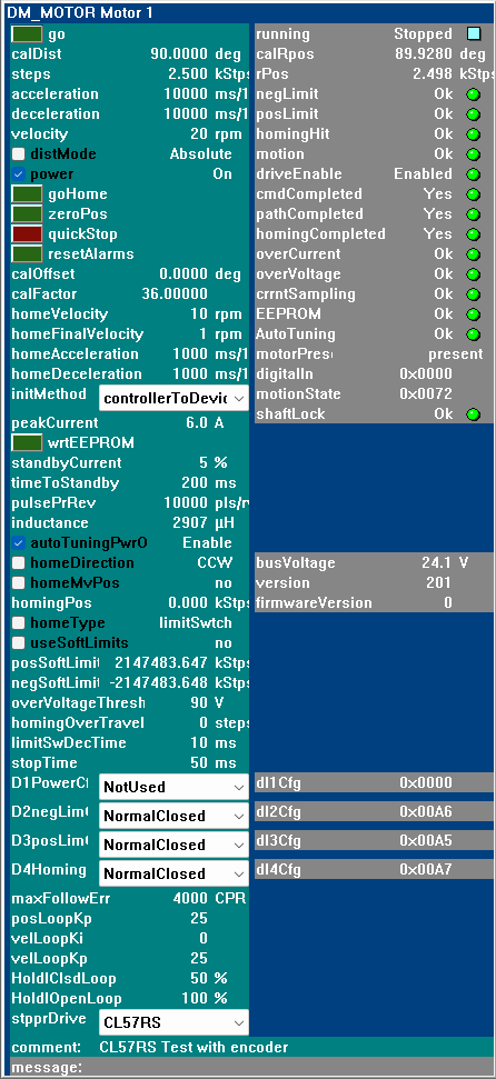
Most of the motor, motor status and control parameters directly relate to the corresponding StepperOnline command and status parameters and will not have further notes here. Right click on the command/status parameters to see more information on a specific parameter. However, a few parameters need a little more information:
go: Go operation, triggers a run of the path PR0 motion. The ConSys device uses motor stepper controller PR0 registers for the motion control. Parameters related to the motion are written to PR0 registers by the 'steps', 'acceleration' and 'velocity' parameters. When the motor is moving the device prioritises updates of motor position and move status bits for the moving motor.
power: The motor power can be controlled either by software (using this control) or by a digital input. The factory default is that the power is controlled by digital input 1 - with power on with open/high input. To use the software 'power' button in ConSys the digital in controlled power must be disabled (see D1PowerCfg) or the digital input must be set 'closed'.
calFactor, calOffset: Used by the device to update between calibrated positions (calDist, calRpos) and the motor control positions (steps, rPos). The calibrated position calRpos = calFactor * rPos + rOffset.
initMethod: The 'initMethod' parameter specifies the direction of initialisation happening each time the communication is established – i.e. at initial startup when the device is enabled/started and at communication reconnection after a communication timeout. The direction can be either ‘controllerToDevice’ or ‘deviceToController’. Remark: The 'initMethod' only affects parameters below 'initMethod' in the Console list view. Parameters above 'initMethod' are always sent from the device to the controller. In normal operation, it is recommended to use the setting ‘controllerToDevice’. The setting ‘deviceToController’ can be used in situations where some of the settings below initMethod are often changed and not wanted to be stored to the controller EEPROM on change. If used in this way, it is still recommended to store the fixed values to the EEPROM (like the use if the digital inputs).
wrtEEPROM: Triggers the STEPPERONLINE controller write to EEPROM command. Writes all current controller settings to the EEPROM – including the parameters set above ‘initMethod’ and settings set through MotionStudio or found by auto tuning at power on. When writing to EEPROM takes place the controller can not process commands sent to it – updating and control of the controller is therefore skipped by the ConSys device for a short period after pressing the ‘wrtEEPROM’ button. The ‘wrtEEPROM’ button is released at the end of the dead period and update starts again. After writing to the EEPROM it is recommended to check the persistent settings stored in the controller by selecting the ‘initMethod’ ‘controllerToDevice’, power off the controller for a minute, repower the controller and check the settings read from the controller.
autoTuningPowerOn: Auto-tuning at power on. Default set true in factory settings. When true the controller will tune and adjust ‘inductance’, current loop KI, KP,Kc at controller power up. However, the inductance found for some motors (the WindTunnel linear drive) have been seen to vary quite a bit from time to time (and maybe most if the motor is not ‘enabled’ when the STEPPERONLINE controller is powered on) – so maybe it is best run once with auto tuning on, then set a fixed inductance, write settings to EEPROM and finally leave ‘autoTuningPowerOn’ in state ‘off’.
homeMvPos: If ‘homeMvPos’ is set, the controller will move to the specified position,’homingPos’, after homing. WARNING: !! Limit switches are ignored during the move to 'homingPos' !!. If ‘homingPos’ is outside the limit switches the motor will move to this position even if the limit switch is passed. Note: Generally when using homing to find the zero position, the motion is decelerating to stop when the homing switch is hit. Depending on the final homing speed the final stop position after homing will not be zero but a little away from zero position. If the drive should end at the actual zero position after homing, check ‘homeMvPos’ and set ‘homingPos’ to zero. In this way the motor will move back to the zero position after homing stop.
homingPos: The position moved to after a homing as described above. Since limit switches are ignored by the driver when moving to 'homingPos', for safety reasons the ConSys device requires soft limits to defined – and the ‘homingPos’ to be within the soft limits.
useSoftLimits: Enable/disable use of soft limits. If soft limits is set, the motor movement will stop at the limits set by ‘negSoftLimit’ and ‘posSoftLimit’. Remark however that the ‘negLimit’ and ‘posLimit’ status bits will not light up as these are the read status of the digital input bits D2 and D3.
D1PowerCfg: DI1(input 1) configuration. Not used directly in the device, but factory default is power enable, ‘normal opened’ to, i.e. if not changed from default and not set high, the motor power will be enabled at power on (and not possible to control by the software control parameter ‘power’. Can be set to ‘NotUsed’|’NormalClosed’|’NormalOpened’ from the ConSys device. If the read back value ‘dI1Cfg’ does not match one of the predefined modes in ConSys, ‘D1PowerCfg’ will have the value ‘Fail’. This will be the case if the digital input D1 has been configured for another purpose using MotionStudio.
D2negLimCfg, D3posLimCfg, D4HomingCfg: DI2-DI4 (Digital input 2-4) configuration. As described in Use of digital inputs these bits are used in the ConSys StpprOnlnModbusDevice for limit switches and homing switch. Can be set to ‘NotUsed’|’NormalClosed’|’NormalOpened’ from the ConSys device. If the read back value ‘dIXCfg’ does not match one of the predefined modes in ConSys, ‘D2XXXCfg’ will have the value ‘Fail’. It is strongly recommended to store the configuration of the digital inputs in the EEPROM using ‘wrtEEPROM’ (or the MotionStudio utility program).
motorPresent: The ‘motorPresent’ status can have the following values:
0: notInConfigFilter, Not defined in configuration filter: The motor is not in the motors to search for at connection/startup. See also Device Configuration.
1: notPresent: There is no response from the controller, so the motor cannot be controlled.
2: present: The motor is found (responded) during the initial search.
maxFollowErr, posLoopKp, velLoopKi, velLoopKp, HoldIClsdLoop, HoldIOpenLoop: These parameters are only used by the drivers with for motors with encoder (CL57RS and CL86RS), and are therefore only set/updated if these kind of drives is specified in 'stpprDriver'.
stpprDriver: Select the stepper driver used for this motor. Must be one of the supported driver types: DM556RS, DM882RS, CL57RS or CL86RS. Can only be set when communication is disabled. The commands availeble and the accepted value ranges for some parameters depend on the driver type.
digtitalIn: The digital input word as read from the controller. (negLimit, posLimit, ...).
motionState: The motion state status word as read from the controller. (driveEnable, pathCompleted, ...)
comment: Comment set by user.
Common device status and control parameters
Device status and control console view
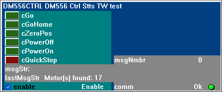
cGo, cGoHome, cZeroPos, cPowerOff, cQuickStop: Trigger/broadcast a common command to all motors/controllers. The motors will perform the triggered action simultaneously.
cPowerOff, cPowerOn: Trigger/broadcast a common power on/off of all motors. Will also check/uncheck the motor 'power' control buttons for all present motors.
enable: Enable/disable the device serial communication. Remark: the actual enabling/disabling of the communication in the device is not handled directly by this button. The state of the button just ‘signals’ the device to change operational state. The device will perform the actual enable/disable as soon as posible after the change of state. This is made to ensure that the enable/disable action does not disturb the communication reconnection in the timeout handling in the device. The ‘msgStr’ will keep you updated of the actual communication state.
Error and message numbers
The error and message numbers '.msgNmbr':
| Number | Origin | Type | Message |
| 100 | StpprOnlnModbusDevice | Message | Connect: Searching for motors/controllers |
| 101 | StpprOnlnModbusDevice | Message | Saving controller parameters to EEPROM |
| 200 | StpprOnlnModbusDevice | Message | Motors/controllers responding during search |
| 201 | StpprOnlnModbusDevice | Warning | Wrong controller RS485 id/address returned from driver |
| 2000 | SerialPortCalcDevice | Error | Read thread exception |
| 2001 | SerialPortCalcDevice | Error | TCP communication error |
| 2002 | SerialPortCalcDevice | Error | MOXA no ping response |
| 3000 | SerialPortCalcDevice | Message | Reconnecting - disconnect |
| 3001 | SerialPortCalcDevice | Message | Reconnecting - enable port |
| 3002 | SerialPortCalcDevice | Message | Reconnecting - stop logging |
| 4000 | ModBus485BaseDevice | Error | ModBus Exception |
Device initialisation
When the device communication is started – either at startup, after communication is enabled or by communication reconnection after a timeout – the following happens:
- The communication is opened.
- A check command is sent to all STEPPERONLINE controllers with the active bit flag set in the device setup motor search filter.
- All controllers that respond to the check command are synchronized with the StpprOnlnModbusDevice
- Parameters below ‘initMethod’ in the console are written to controller/read from controller as specified by the ‘initMethod’
- Parameters above ‘initMethod’ are sent to the controller.
- Operational status update and control starts.
Device use of digital inputs (for homing and limit switches):
The ConSys StpprOnlnModbusDevice defines the use of some of the digital inputs. These inputs must be configured in the STEPPERONLINE driver hardware to match the ConSys device use of inputs. It is recommended to store the operation mode settings (not used, normal opened, normal closed) in the STEPPERONLINE digital driver EEPROM. This can be done either by the STEPPERONLINE MotionStudio program or directly from the ConSys device.
DI1: Factory default is 'Power enable' (Default enabled if connection open). This input is not directly used by the ConSys device, but may need to be changed from factory default to allow control of power enable from device 'power' parameter.
DI2: Negative limit switch.
DI3: Positive limit switch.
DI4: Homing switch.
Device Configuration
How to setup a new ConSys device for the STEPPERONLINE controller:
- Using Access, define the device in the SQL 'DeviceLocation' table. Use an appropriate 'DeviceId', Fill in 'FrontendId' and 'LoaderInstance' and set 'DeviceTypeId' to 4 (VdCalc based devices)
- When the device has been defined in the 'DeviceLocation' table, use the DatabaseEditor for the rest of the configuration.
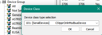
- In the tree view, open 'Device Group', and in this, right click on the group in where to define the device and select 'New':
- In the 'Device Class' dialog that pops up, select 101: [SerialDevices] 'CSttpOnlnModbusDevice':
- Configure the device in the 'Device Configuration' dialog
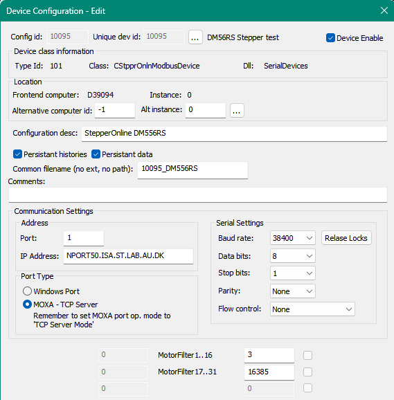
Fields in the Device Configuration dialog:
I0: 'MotorFilter1..16': Bit 0..15 of motor search filter
I1: 'MotorFilter17..31': Bit 16..30 of motor search filter
The motor search filter (32 bit word composed of I0 (low bits) and I1 (high bits)) specifies the driver addresses/id’s to search for during device initialization. Bit 0 set will include motor 1 search, bit 1 motor 2,...,bit 15 motor 16, bit 16 (hw bit 0) motor 17 … bit 30 (hw bit 14) motor 31. If no bits set, all motors will be included in the search (i.e. the same as setting all bits).
Example:
I0: 3, 0x0003 => Include motor 1 and 2 in search.
I1: 16385, 0x4001 => Include motor 17 and 31 in search.
Common filename (no ext, no path): The filename base used for files stored by the device.
File types:
.hst: History file. Store the device histories for device parameters.
.cpd: ConSys Persistent Data: Store persistent stored device parameters.
MOXA Configuration
MOXA setup, used under development, tested with MOXA IA5450A
Serial Settings (Must be set if used with DocLight or similar for test communication)
Baud rate: 38400
Data bits: 8
Stop bits: 1
Parity: None
Flow control: None
FIFO: Enable
Interface: RS-485 2-wire

Operational Settings used:
Operation mode: TCP Server
TCP alive check time: 1 min
Inactivity time: 0
Max connection: 2
Ignore jammed IP: No
Allow driver control: No

Packing length: 0
Delimiter 1: Disabled
Delimiter 2: Disabled
Delimiter process: Do Nothing
Force transmit: 100 ms
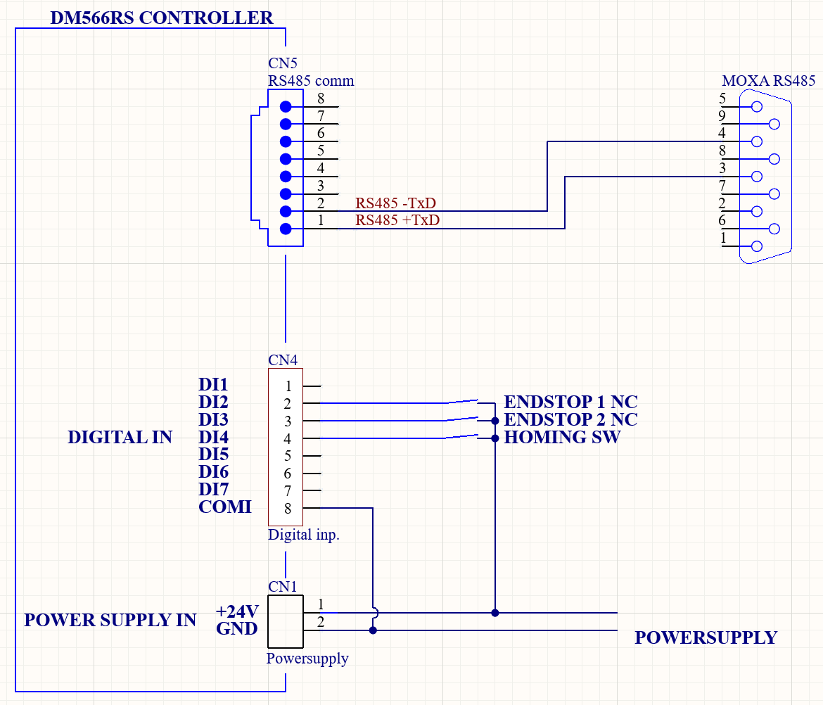
DM556RS wiring and configuration
DIP switch settings
SW1-SW5: Must be set to the RS485 address to be used with the controller. Must be changed from default to an address in the range 1..31. Address 0 is used for broadcast commands to all controllers and can therefore not be set as an individual controller address.
SW6,SW7: Set baud rate according to the baudrate configured in the ConSys device settings. The device is tested/developed using baud rate 38400, SW6: off, SW7: on.
SW8: Terminal resistance. Enable on last conrtoller in the daisy chain, disable on all other controllers.
RS485 serial cable - wiring of cable used in test setup using MOXA IA5450A with 9 pin DSUB and
Limit switch and home switch wiring:
The STEPPERONLINE MotionStudio utility
The STEPPERONLINE MotionStudio.exe test/configuration tool can be downloaded from STEPPERONLINE. The version used at test time can be found in the documentation directory:
'..\Nat_ISA-Lib\ManualsAndDrivers\StepperOnline\DM556RS_ModBusRS485StepperDriver'
For MotionStudio to run in Windows 11, the folder containing MotionStudie.exe must be copied to a folder on the local computer. If the program is not allowed to run, try to right click on the MotionStudio.exe file, choose properties and check 'unblock program'.
Please note that the Leadshine version of the MotionsStudio can not/should not be used with the StepperOnline stepper drivers.
The MotionStudio communicates through the RS232 port on the stepper driver and can be run in parallel with the RS485 communication used by the ConSys device. Remark however that if you change settings through the MotionStudio the settings are NOT updated in the ConSys interface. If you change parameters with MotionStudio which are also controlled by the StpprOnlnModbusDevice, disable and re-enable the device communication in the ConSys device to synchronize the settings. Almost all configuration parameters are implemented in the ConSys StpprOnlnModbusDevice, so in most situations the MotionStudio program should not be needed. If you need additional settings - or settings that cannot be set by the ConSys device - to be set by MotionStudio remember to store the settings to the EEPROM from MotionStudio (If done with ConSys communication enabled the ConSys communication will timeout and trigger a reconnect.)
Last Modified 01 July 2026