
Hot Planetary SurfacesProvided by: The Planetary Emissivity Laboratory (PEL) at DLR Berlin Homepage: |
Scientific Contact:J. Helbert and A. Maturilli |
Local administrative contact (once a TNA visit is awarded):Ulrike Stiebeler |
Facility Description
|
Analyzing the surface composition of planets from orbit is in general a challenging task. For target bodies with hot surfaces like for example Mercury or Venus, this task gets further complicated by the change in emissivity spectra due to the high temperatures. In support of the National Aeronautics and Space Agency's MErcury Surface, Space ENvironment, GEochemistry and Ranging (MESSENGER) mission and especially in preparation for the Mercury Radiometer and Thermal Infrared Spectrometer (MERTIS) instrument on the BepiColombo mission of the European Space Agency and the Japan Aerospace Exploration Agency [Benkhoff and Helbert 2006], the Planetary Emissivity Laboratory (PEL) at Deutsches Zentrum für Luft- und Raumfahrt (DLR) in Berlin has been completely refurbish with respect to the setup reported in Maturilli et al 2006,2007. The upgraded PEL allows measurement of the emissivity of planetary analogue materials [Helbert et al. 2007, Maturilli et al. 2008] at grain sizes smaller than 25 µm and at temperatures of more than 400°C, typical for example for Mercury's low-latitude dayside (see for example Helbert et al. [2009]). The application is not limited to planetary ob-servations. Many process in industrial applications heat up materials to temperatures of up to 500°C. Little is know so far about the changes in the optical properties of these materials during the heating cycles. The PEL: The Institute for Planetary Research has an expertise in spectroscopy of minerals, rocks, meteorites, and organic matter, build up in more than two decades. The available equipment allows spectroscopy from the visible to TIR range using bi-conical reflection and emission spectroscopy. The institute has an outstanding heritage in designing and building infrared remote-sensing instruments for plane-tary missions. The PEL has been operating in various confi-gurations for the last 10 years. The laboratory experimental facilities consist of the main emissivity spec-trometer laboratory, a supporting spectrometer laboratory for reflectance measurements, sample prepa-ration facilities and an extensive collection of rocks and minerals [Maturilli et al. 2006]. The heart of the spectroscopic facilities is the Planetary Emissivity Laboratory (PEL) which has been completely refurbished in the last two years. The PEL allows currently to measure the emissivity of planetary analogue materials from 3-50 µm for very fine grained samples. The high temperature chamber: In the last step of the upgrade a planetary simulation chamber has been installed in the PEL. This new chamber can be evacuated so that the complete optical path from the sample to the detector is free of any influence by atmospheric gases. The chamber has an automatic sample transport system which allows to maintain the vacuum while changing the samples. The main highlight however is an induction heating system that is permanently installed in the simulation chamber. This answers the main challenge to obtaining emissivity measurements at elevated temperatures which is heating the sample without heating the sample environment. The PEL uses a new and novel approach for heating the samples. Instead of a placing the sample cup on a heater and heating the sample cup by thermal conduction, the samples are placed in a stainless steel cup that is heated by an induction system. In the laboratory setup, a Linn Hightherm HTG-1500 induction heating system with an output power of 1.5 kW is used with a copper pancake coil. An alternating current in the pancake coil with a frequency between 200 and 450 kHz creates an alternating magnetic field, which generates eddy currents within the steel of the sample cup. The electrical resistance of the steel leads to Joule (or resistive) heating of the material. The steel cup heats the sample by conduction. The inductance of the coil has been dimensioned by the manufacturer specifically to match our steel sample cups so that the magnetic field does not reach the sample. The principle of the induction system ensures that only the steel cup is heated while the surrounding including the copper coil remains cold. It allows to heat the samples to temperatures of at least 700K allowing measurements under realistic conditions for the surface of Mercury or Venus. Per-formance tests have shown that the induction system can heat up sample to well above 1000K and keep the sample very stable at these temperatures. If necessary these temperatures can be reached within a few minutes. |
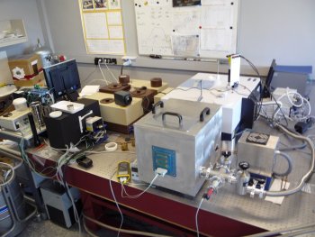 Figure 1: View of the main facility in the PEL (in this call the facility on the right is offered only) 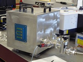 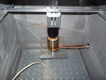 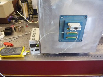 Figure 2 Top: High temperature vacuum chamber during installation - Middle: Inside view without the automatic sample transport system - Bottom: Electrical connector panel |
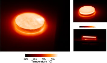 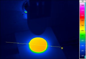 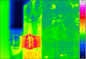 Figure 3 Left: Test of temperature homogenity with induction heating - Middle: View inside the open chamber with heated sample - Right: Outside view of chamber while sample inside is at 700°C Figure 3 top shows a study of the temperature distribution across the sample using an FLIR Therma-CAM P25 thermal imager [Helbert et al. 2009]. A steel cup filled with a quartz sample with a grain size of less than 25 µm was imaged to study the temperature distribution across the sample. For the test the sample was placed on the induction system outside the cham-ber to permit a good view of the sample. We can as-sume that the conditions within the chamber are actually more stable, so measurements on the table are a worst case scenario. The spectrometer effectively integrates across the field of view with an unknown weighting function. Therefore it is desirable to have as little temperature variation as possible across the sam-ple. The image on the left side of Fig. 3 shows the temperature distribution across the sample. The sample has a mean temperature of 460.6°C with a standard deviation of 3.1°C. The biggest temperature variation is seen on the right side, where a thermoele-ment is glued to the cup. The cement used to fix the sensor is not completely even and influences the quartz on top of it. The views on the right side of Fig. 3 (especially the bottom image) demonstrate clearly the benefits of the induction heating system. The sample at 460°C is the main source of thermal radiation. The environment is visible in the thermal images only because of reflected thermal radiation from the sample and the sample cup. This means that influences on the spectral measurement by the environment are effectively minimized. Figure 3 middle shows a view in the (open) chamber during heating, while the bottom panel shows the outside. It can be clearly seen that the very hot sample has no influence on the chamber, underlining the benefits of the induction heating system. Example of spectral effects: As a first test for the high-temperature spectroscopy, spectra of quartz with a grain size of less than 25 µm were obtained [Helbert et al. 2009]. This kind of sample is routinely used for calibration purposes in the PEL, and example spectra can be seen in Maturilli et al. [2008]. | |
|
Figure 4 shows the spectra obtained at 185°C, 391°C, and 461°C in comparison with a reflectance spectrum from the ASTER database (Baldridge et al., 2009) converted to emissivity using Kirchhoff’s law. The temperature of each sample has been obtained by assuming an emissivity of 1 for the Christiansen fea-ture. The calibration method is discussed in detail by Maturilli et al. (2008) and is based on the standard approach of Ruff et al. (1997). Whereas the 185°C spectrum still resembles the “usual” emissivity spectrum of quartz, the spectra at elevated temperature show significant changes. Most obvious is the change of the characteristic double feature in the Reststrahlen region between 8 and 9 µm. At 491°C one half of the feature almost disappears. In addition a shift in the position of the transparency features is observed, while no shift of the emissivity maximum (Christiansen feature) is seen. As the transparency region is sensitive to the transition from surface to volume scattering, any structural rearrangement would mostly affect this region. Quartz undergoes a displacive transformation from its low or a form (stable at room temperature) to its high or ß form at 574°C (Vassallo et al., 1992). Such a transformation results in a small structural rearrangement, such as a minor rotation of the tetrahedra without bond breaking, and such transitions are usually reversible [Vassallo et al., 1992]. Even though the sample did not reach this temperature, the changing symmetry most likely is responsible for the observed band shifts. |
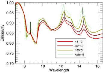 Figure 4 Emissivity spectra of quartz during heating |
|
Summary: The facility offered here, consisting of the vacuum chamber with the induction heating system and the attached spectrometer, is unique in Europe. It enables measurements of optical properties of mate-rials under extreme conditions. The facility is not li-mited to these measurements, as the flexibility of the setup allows to perform a wide variety of measure-ments under extreme temperature conditions. |
|
Facility References
Selected relevant publications
A.M. Baldrige (2009) Remote Sensing of Environment ,in press
J. Benkhoff, J. Helbert, et al. (2006) ASR, 38, p4
J. Helbert et al. (2007), ASR 40, DOI:10.1016/j.asr.2006.11.004
J. Helbert and A. Maturilli (2009), EPSL, in press
A. Maturilli, J. Helbert et al. (2006), PSS 54
A. Maturilli, J. Helbert, et al. (2008), PSS 56
S. Ruff et al. (1997), JGR 102
A. M. Vassallo et al. (1992). Appl. Spectroscopy 46.
For information on the Europlanet TNA programme contact:
Professor N J Mason, Department of Physics and Astronomy, The Open University, Walton Hall. Milton Keynes, MK7 6AA
Email (preferred method of contact)