Specifications of the CD1 beamline
A sketch of the beamline which is located on a bending magnet source is shown below:

- A plane mirror deflecting the beam upwards toward the grating.
- A toroidal grating to disperse the synchrotron radiation.
- CaF2 window to separate the beamline vacuum from air.
- Exit slit.
- CaF2 Photo Elastic Modulator (PEM).
The grating will be a 400 grooves/mm laminar type and is optimized for high 1st order flux and low 2nd and 3rd order flux in the wavelength range of 115-350 nm. The coating of the grating will be MgF2 protected Aluminium, and the MgF2 layer thickness will be optimized by the manufacturer (Carl Zeiss Optronics GmbH.) to give the highest reflectivity at a wavelength of 115 nm. The width of the CD bands are quite wide, typically 20-30 nm, so the beamline will only provide a very moderate resolution of about 1 nm FWHM.
The beamline will be operated as a entrance slit less system. To yield a resolution of about 1 nm, an exit slit size of 1 mm is required. Under these condition the resolution of the entire optical set-up will be exit limited. The exit slit size can be chosen continuously from 0 to 2 mm. As the grating rotates, the grating focus distance changes. This change is very limited, only about 12 mm. Given the moderate resolution required, the grating to exit slit distance needs not be changed during a wavelength scan.
The Exit slit, the PEM and the sample will be placed under a Nitrogen atmosphere, seperated from the beamline vaccum by a CaF2 window.
CD spectroscopy requires that any scattered ligth is effectively reduced/removed. Several baffels are therefore placed along the beamline and in combination with a Zero Order beam Trap near the grating the scattred light is effetively reduced.
| Optic | Major radius | Minor radius | Active area |
|---|---|---|---|
| Mirror | Plane | Plane | 50 mm wide x 30 mm long |
| Grating 400 grooves/mm | 2550 mm | 1337 mm | 70 mm wide x 55 mm long |
Resolution of CD1
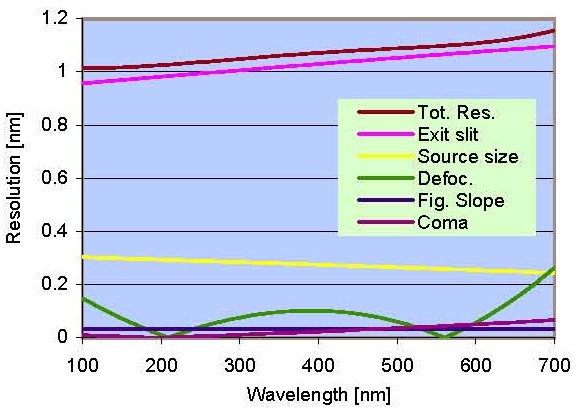
Calculated resolution for the CD1 beamline. The individual contributions from the Exit Slit,
Source size, Defocus, Figure slope error and Coma are shown together with the Total Resolution.
Last Modified 15 May 2012